Project History
The OpenMMS project started in September 2016 with the acquisition of a Velodyne VLP-16 lidar sensor. The initial research goal focused on determining how the inexpensive VLP-16 sensor’s data, along with Simultaneous Localization And Mapping (SLAM) algorithms, could be used for ground-based and aerial, kinematic laser scanning. The wide-open, mostly featureless prairies of Western Canada, were determined not to be the ideal areas for standalone lidar SLAM operations. These were the project areas of most interest to the research. As a result, using only a SLAM-based approach to digitally mapping these types of areas was abandoned. The research goal then shifted and focused on developing a lower-cost mobile mapping system using desktop manufacturing techniques, standard tools, and off-the-shelf components.
A. OpenMMS Sensor (Version 0.9 - Beta)
Overview
For the OpenMMS Beta sensor (1st generation), the first goal was to design and manufacture a scratch-built mobile mapping sensor that integrated an Applanix APX-15 v2 GNSS-INS sensor, with a Velodyne VLP-16 lidar sensor. The second goal was to determine how the independent datasets from these sensors could be combined to create an accurate point cloud dataset. The last goal was to determine the post-processing software procedure, and what software options (open-source or commercial) were available.
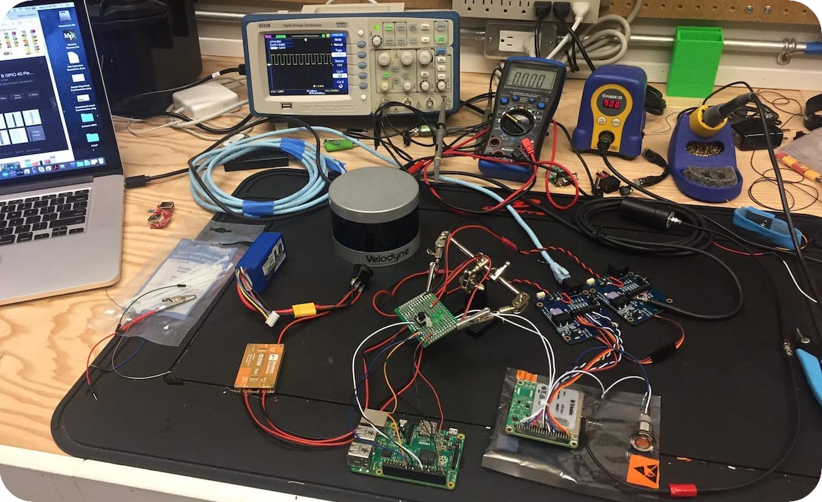
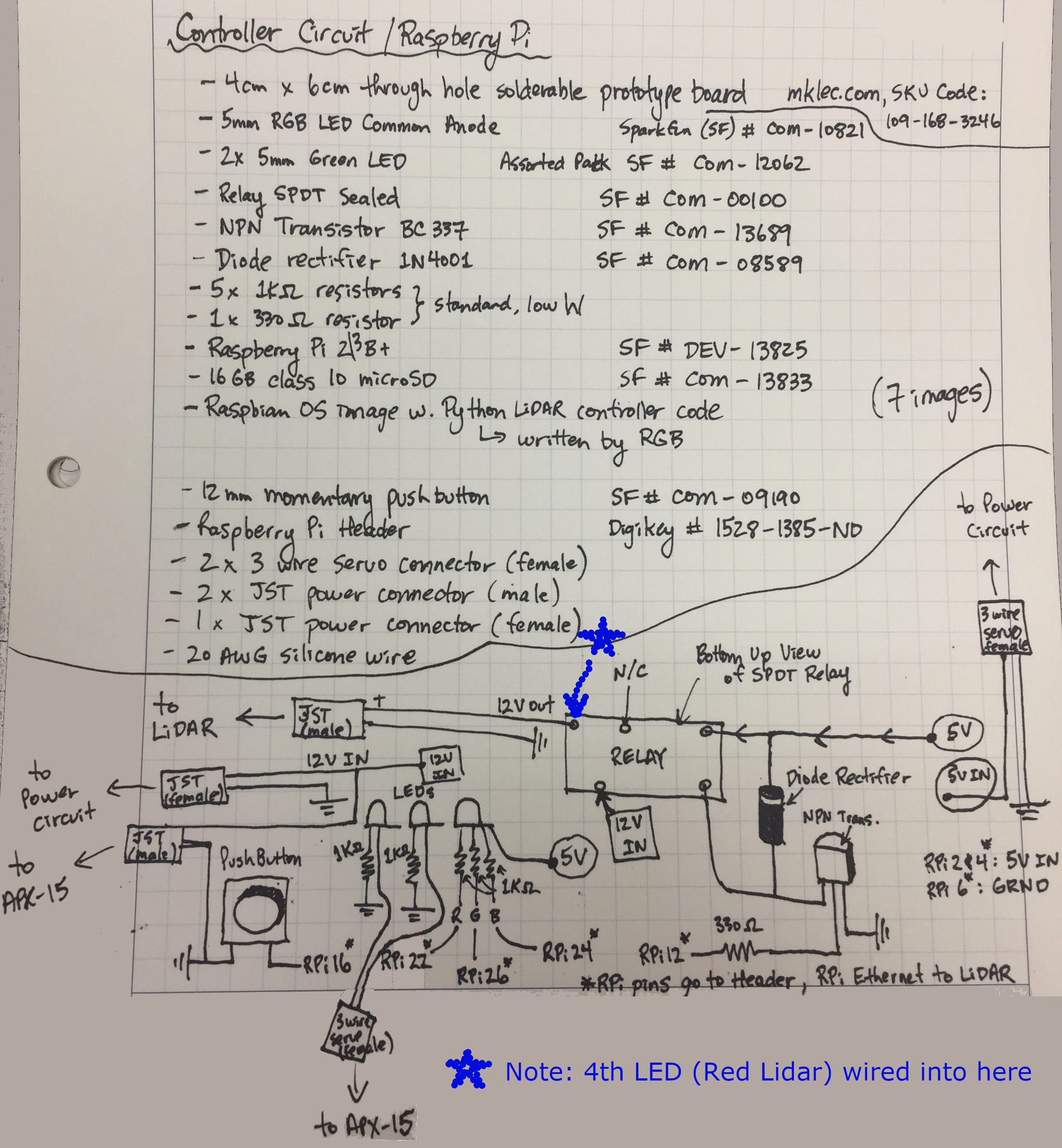
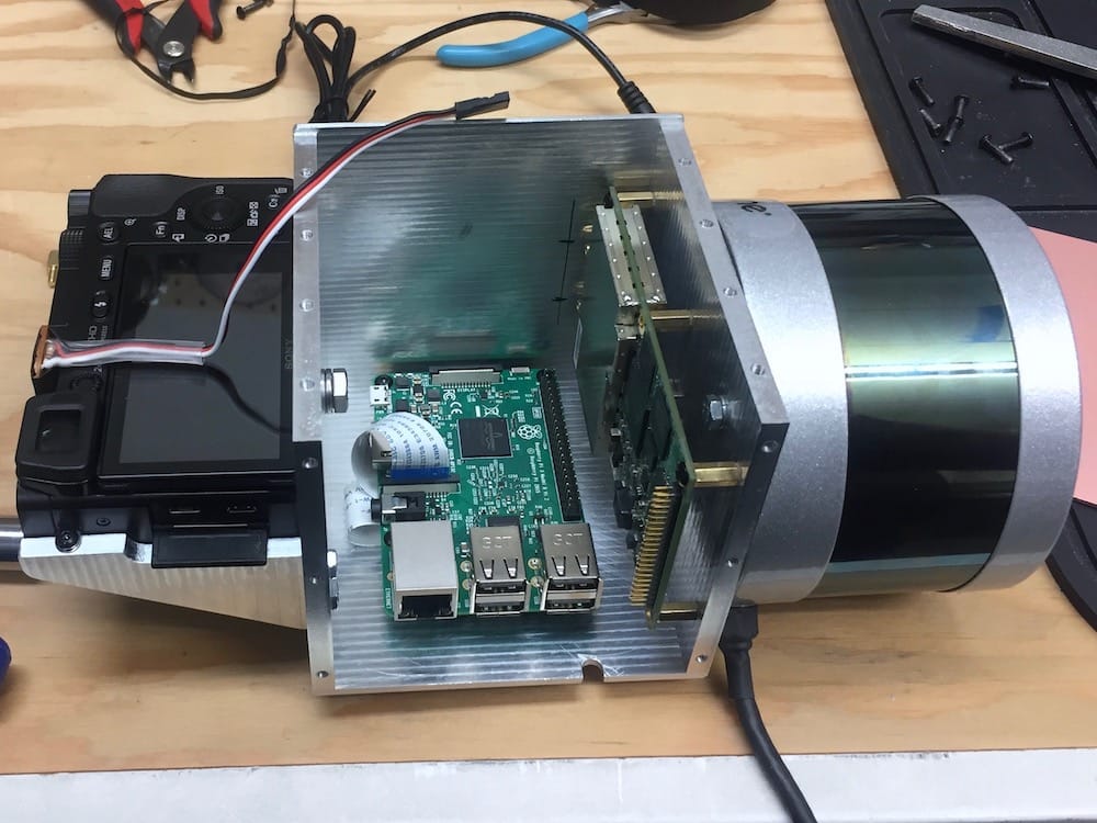
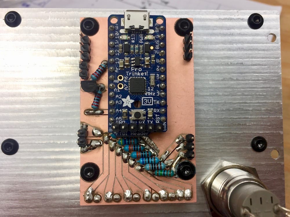
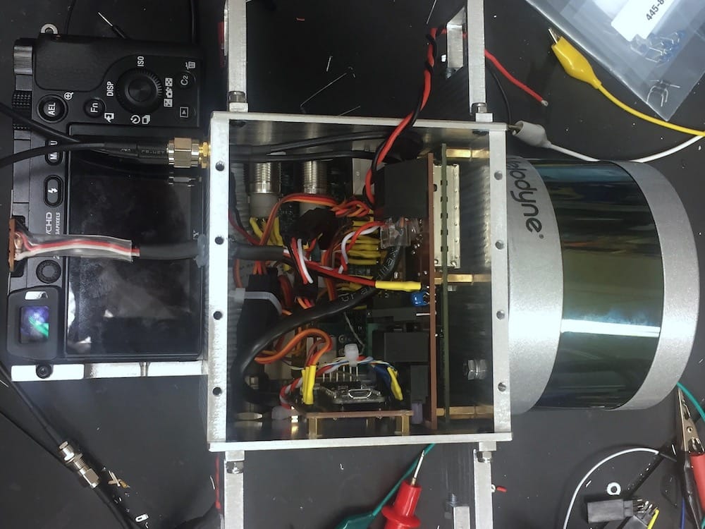
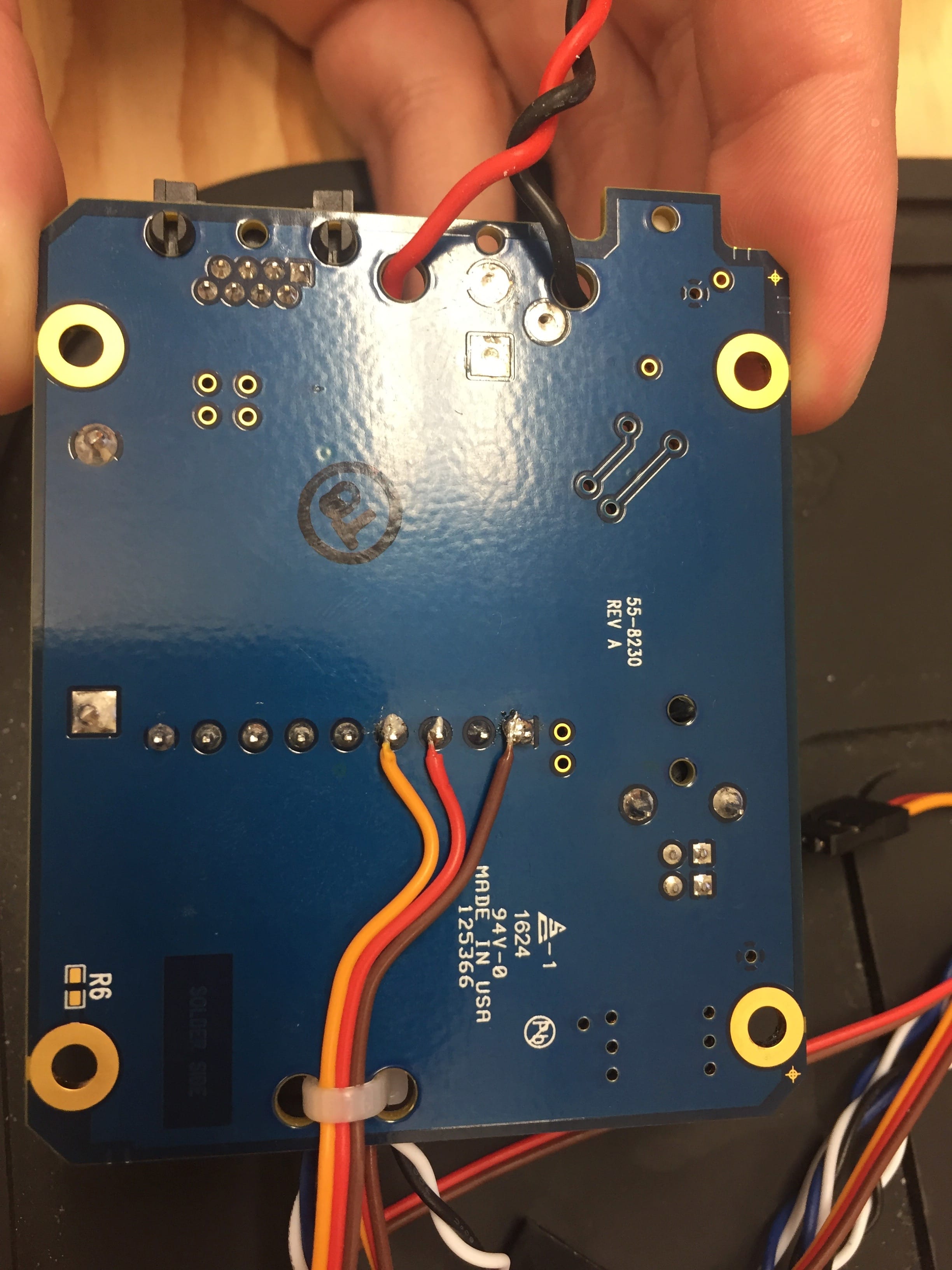
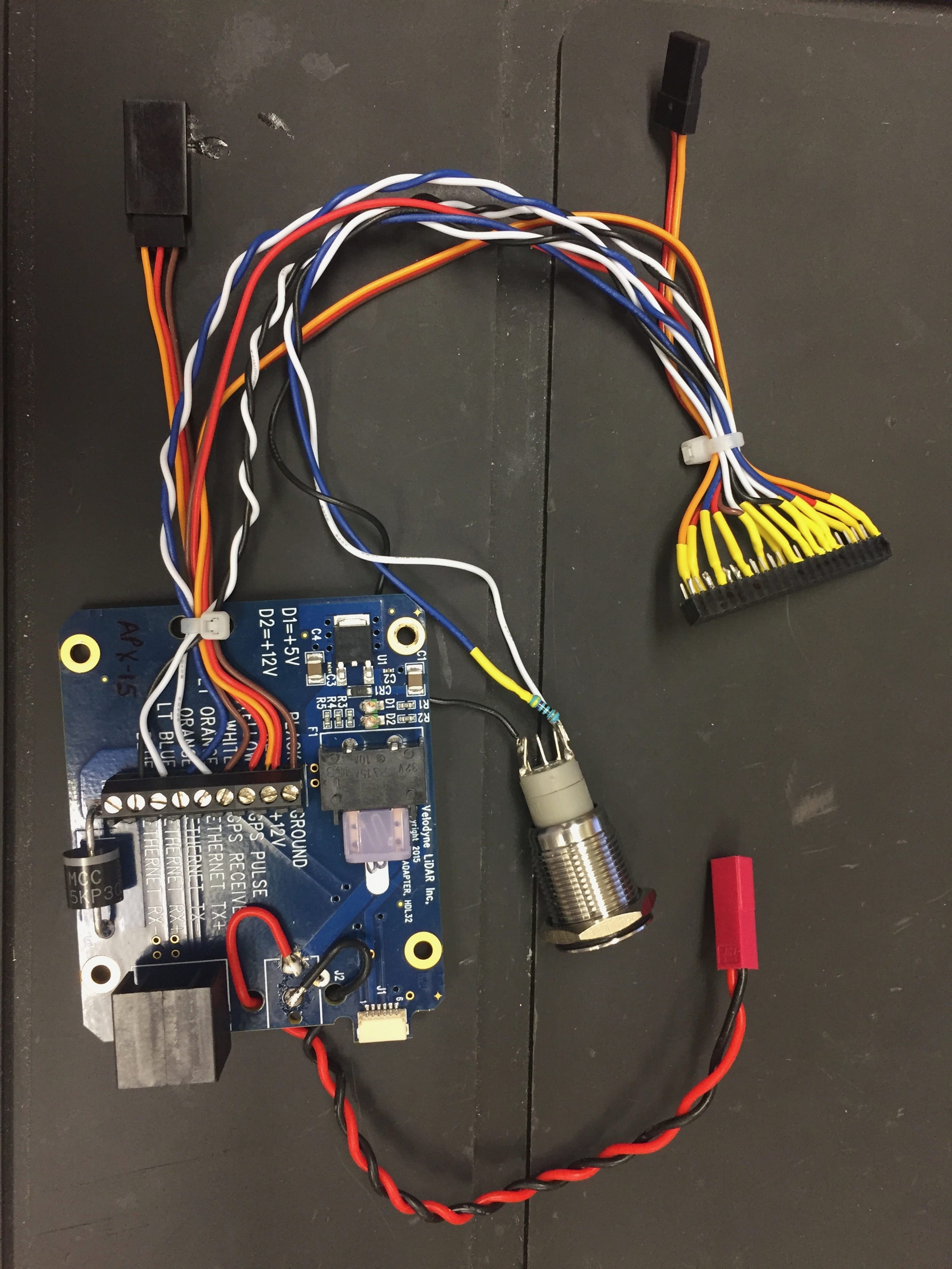
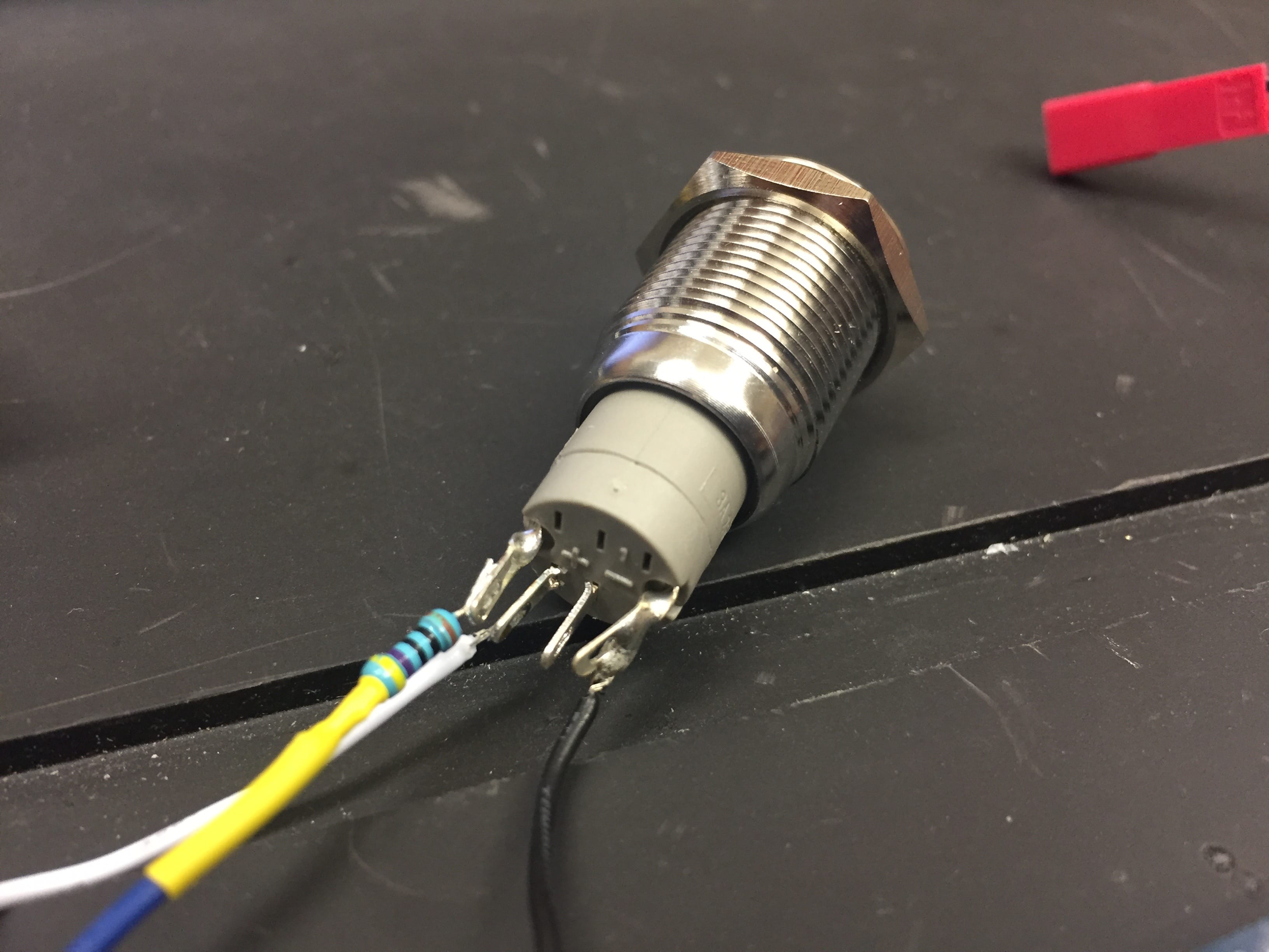
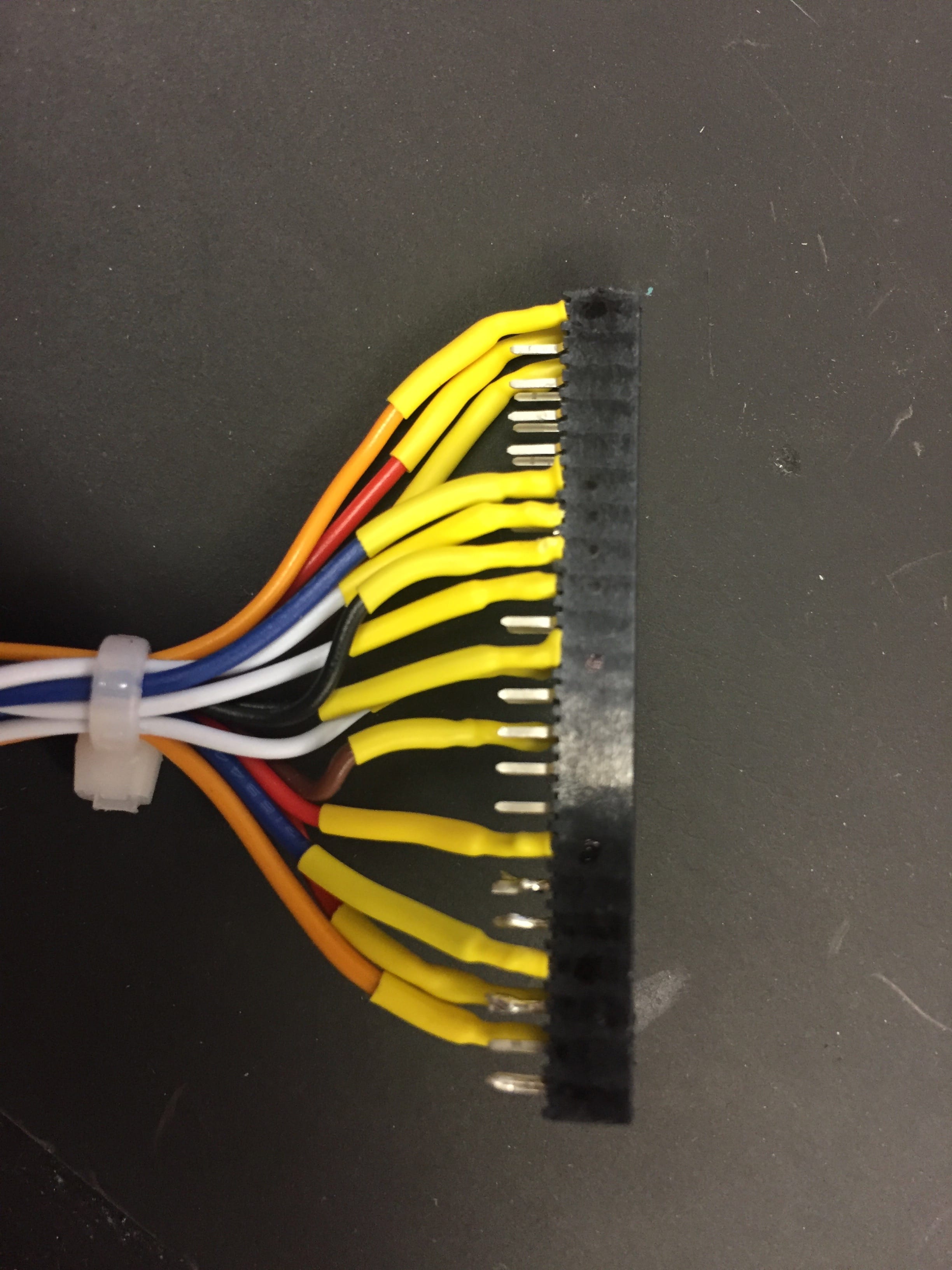
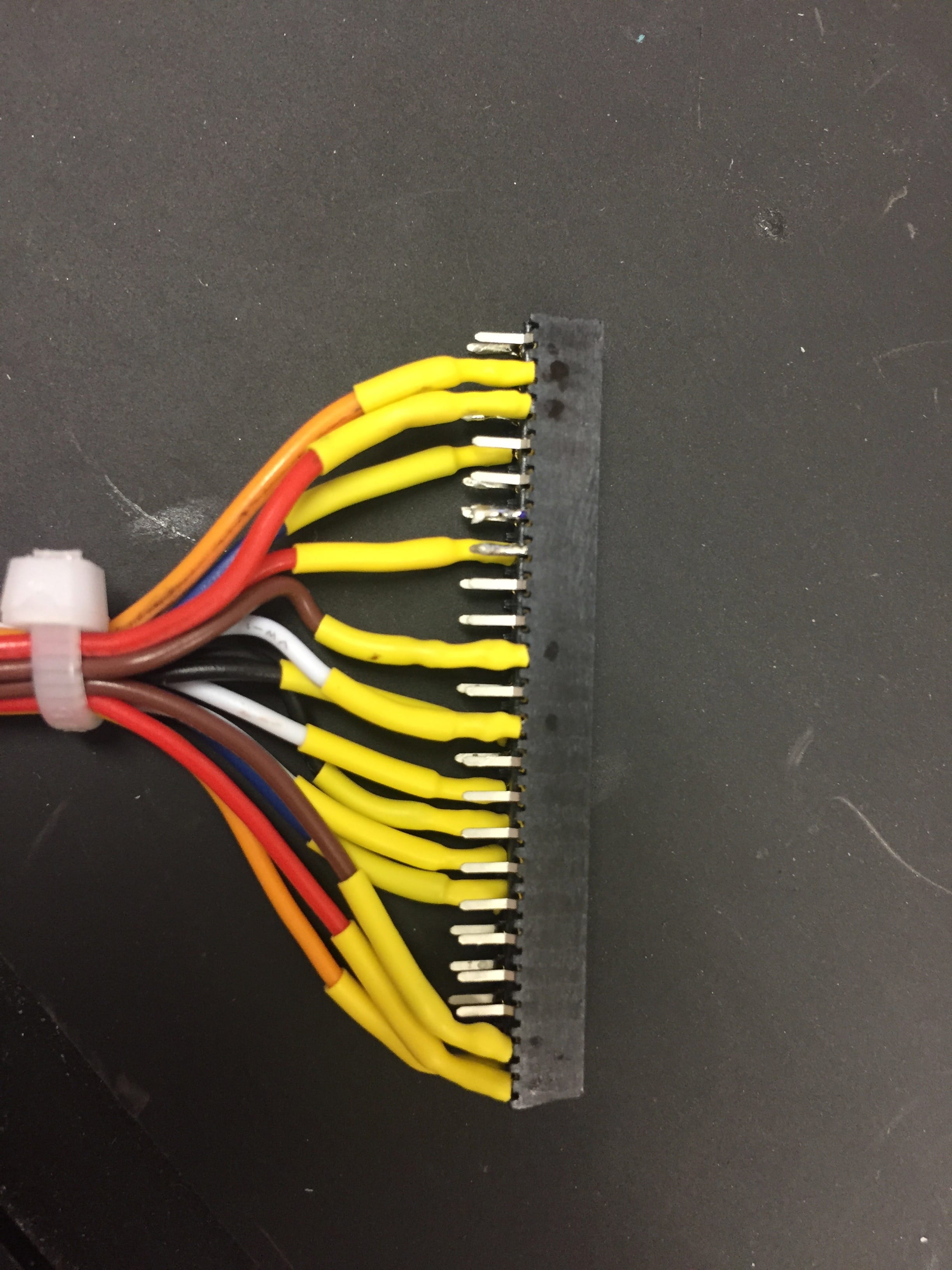
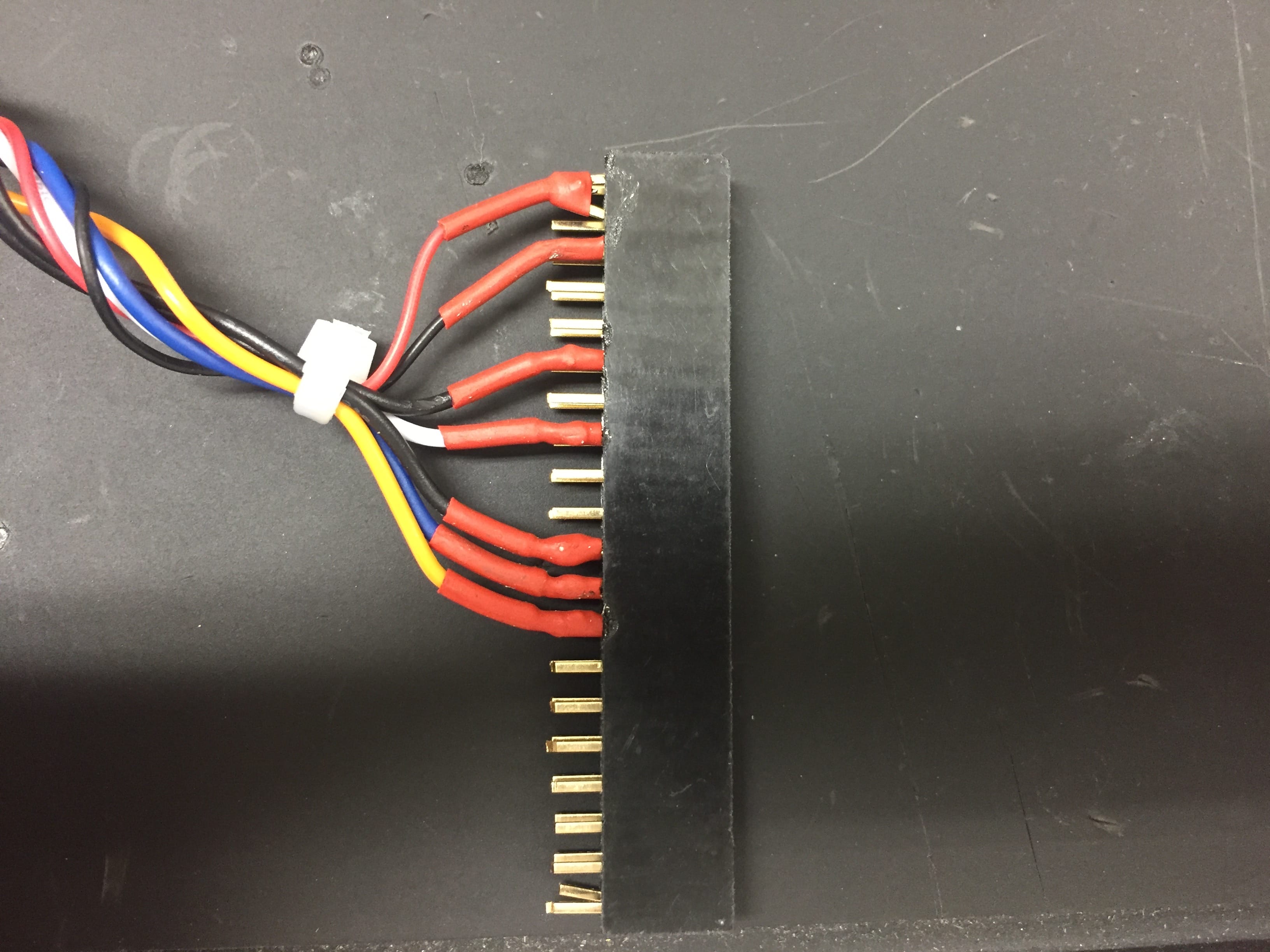
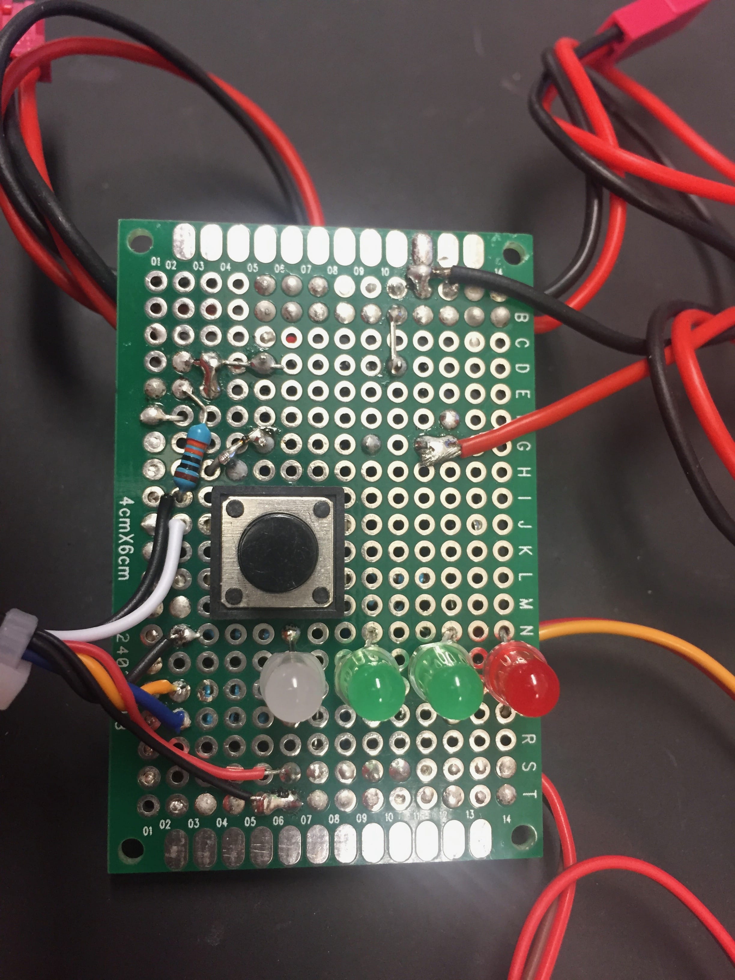
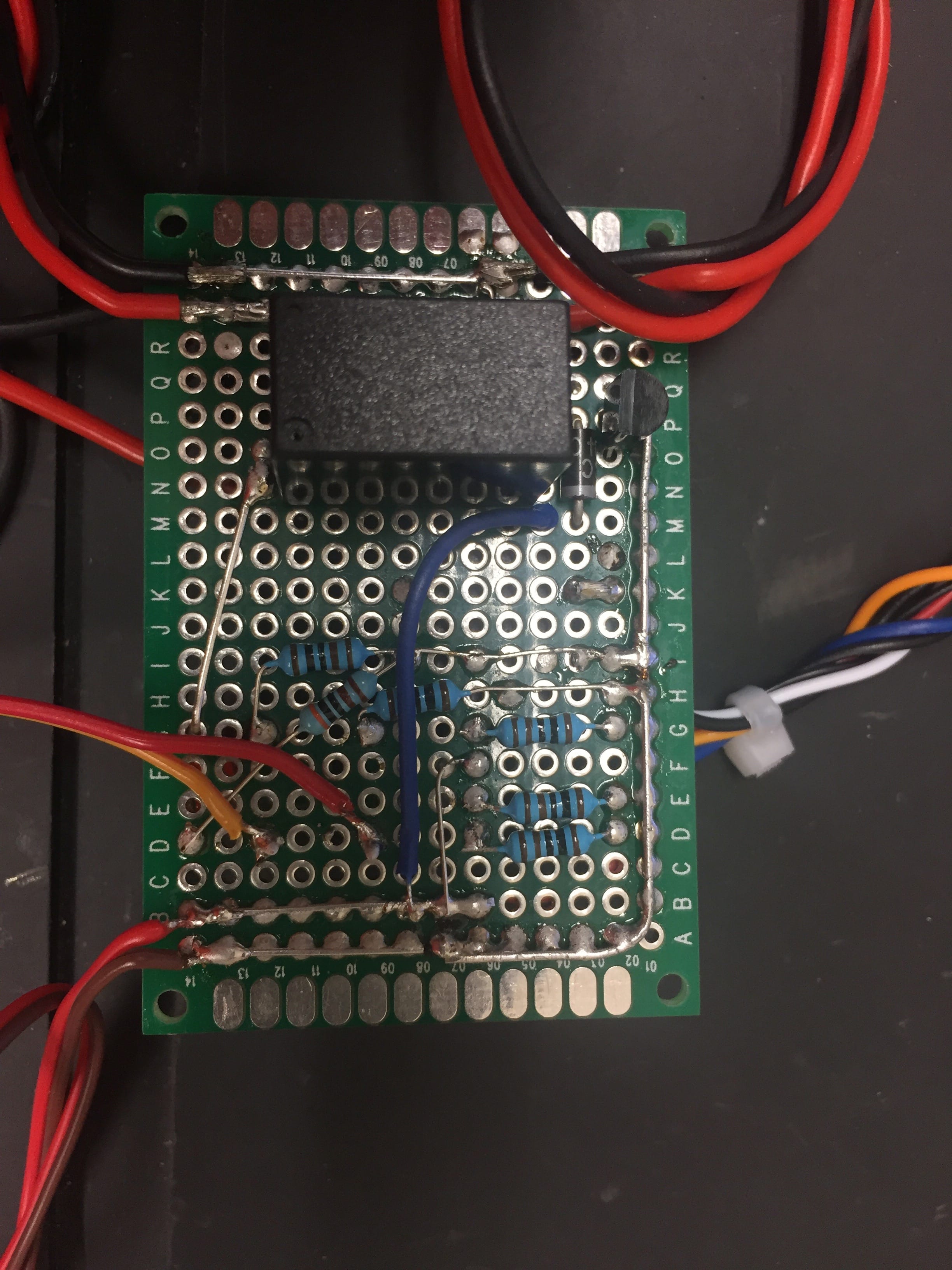
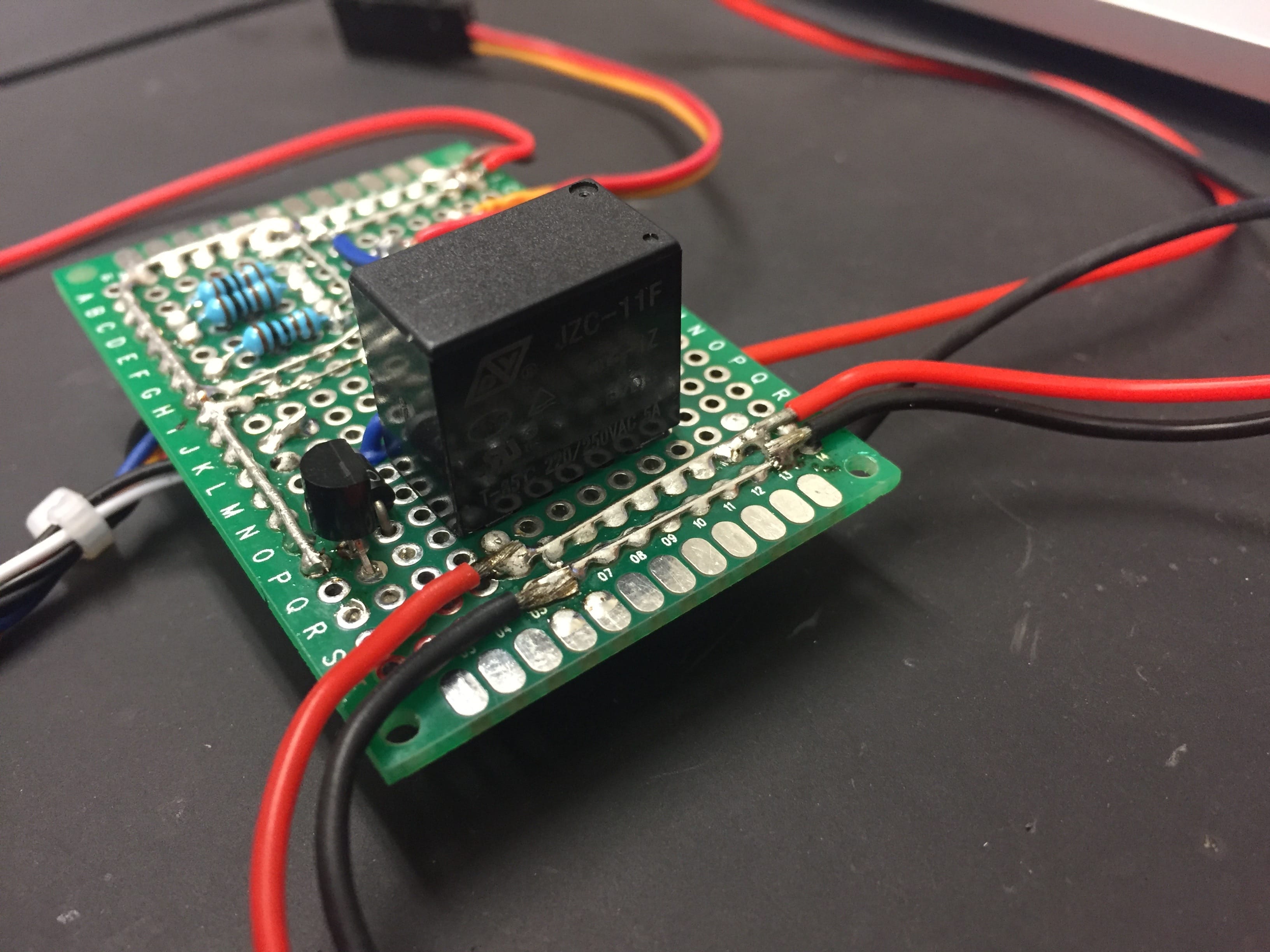
The hardware development and the software/data-processing development proved to be somewhat of a chicken and egg problem. It was unclear how the hardware and software components would need to work with each other to produce the desired deliverables. As a result, the logical starting point for the project was challenging to determine. An iterative development process was used and focused on advancing the hardware and software components simultaneously. The initial Alpha version (proof-of-concept) of the OpenMMS sensor system began with the APX-15, and VLP-16 sensors taped to the inside of a cardboard box. A hand-soldered electronics control circuit connected the necessary data and power wires to the respective sensors and other components (e.g., Raspberry Pi 2 Model B computer).
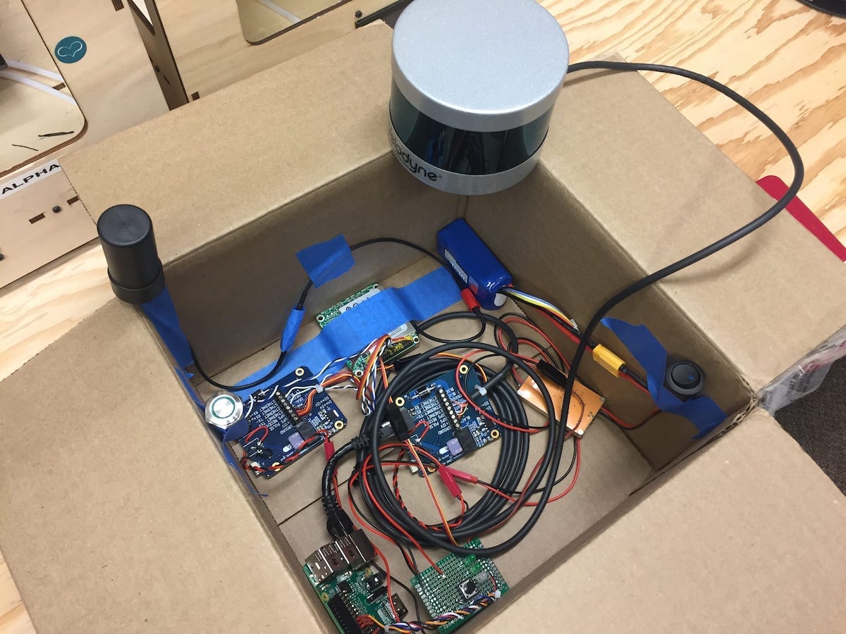
Fig A.1. Alpha version of OpenMMS sensor
Once the Alpha Version was operational, ground-based mapping tests began. The test data collected by the OpenMMS Alpha system allowed for software/data-processing tests to commence. The results of the software testing routinely provided new ideas and improvements for the sensor hardware. This circular development strategy continued until a proven data collection procedure, and a reliable data processing procedure came to fruition. By selecting to use the Applanix APX-15 GNSS-INS sensor for the OpenMMS sensor, the data-processing workflow required the use of Applanix’s POSPac UAV software. A benefit of choosing an Applanix GNSS-INS sensor is the inclusion of a perpetual license for Applanix’s POSPac UAV software with the hardware purchase.
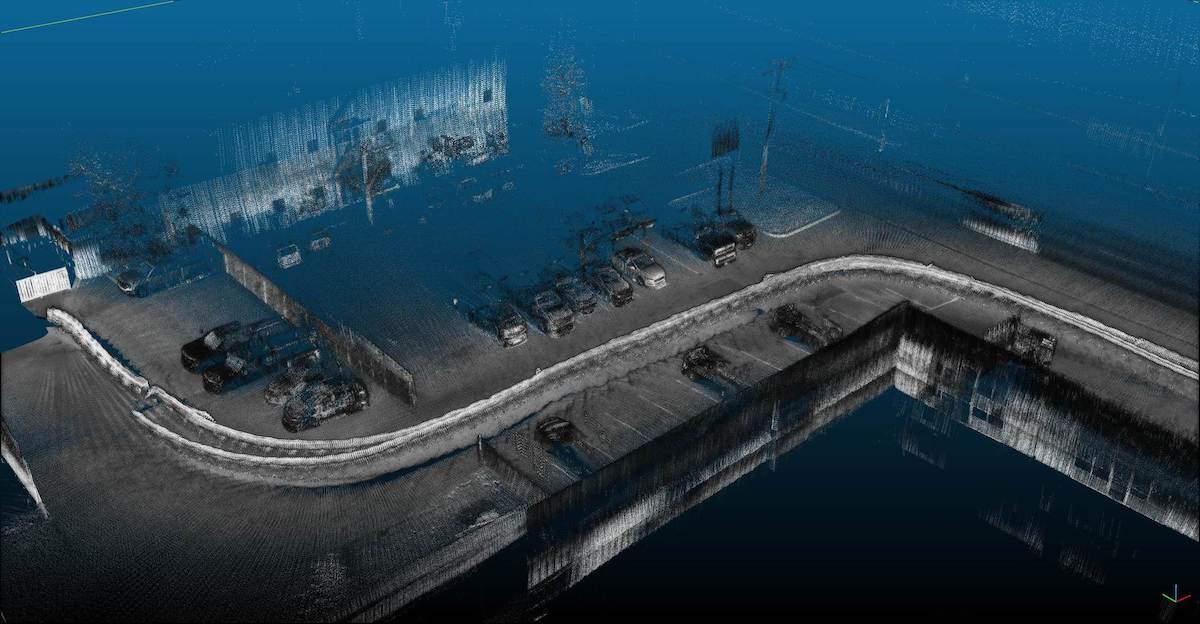
Fig A.2. Initial test map, collected with the Alpha Box while walking
The POSPac UAV software processed the proprietary Applanix GNSS-INS .T04 data file collected by the APX-15 sensor and GNSS data from a reference station, to produce a Smoothed Best Estimated Trajectory (SBET) for the Velodyne VLP-16 lidar sensor. The vital information within the resulting SBET data includes the position and orientation estimates for the lidar sensor at precise moments in time. The lidar observations were stored in the binary .pcap file format and were parsed out and fused with the SBET data using the timing data as the link. Dr. Ben Wilkinson, a professor within the Geomatics department at the University of Florida, graciously provided the initial Python2-based software application for parsing the binary lidar observations and fusing them with the SBET data. The result was a georeferenced point cloud in an ASCII-based comma-delimited file (.csv). The point cloud was opened in the powerful, open-source software, CloudCompare for visualization and further analysis.
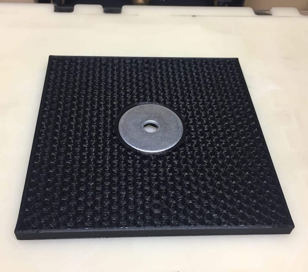
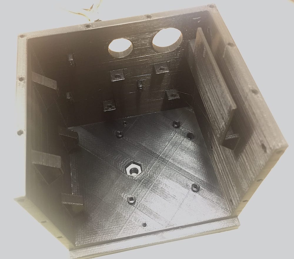
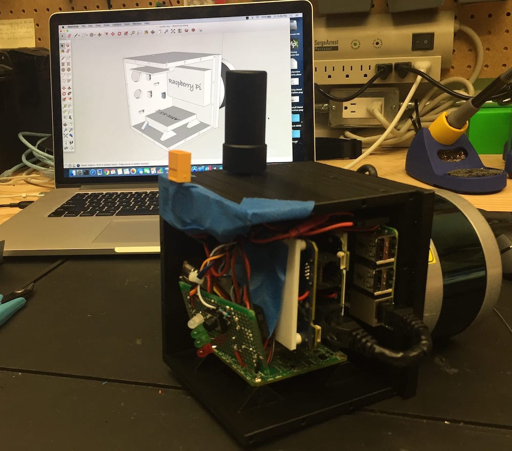
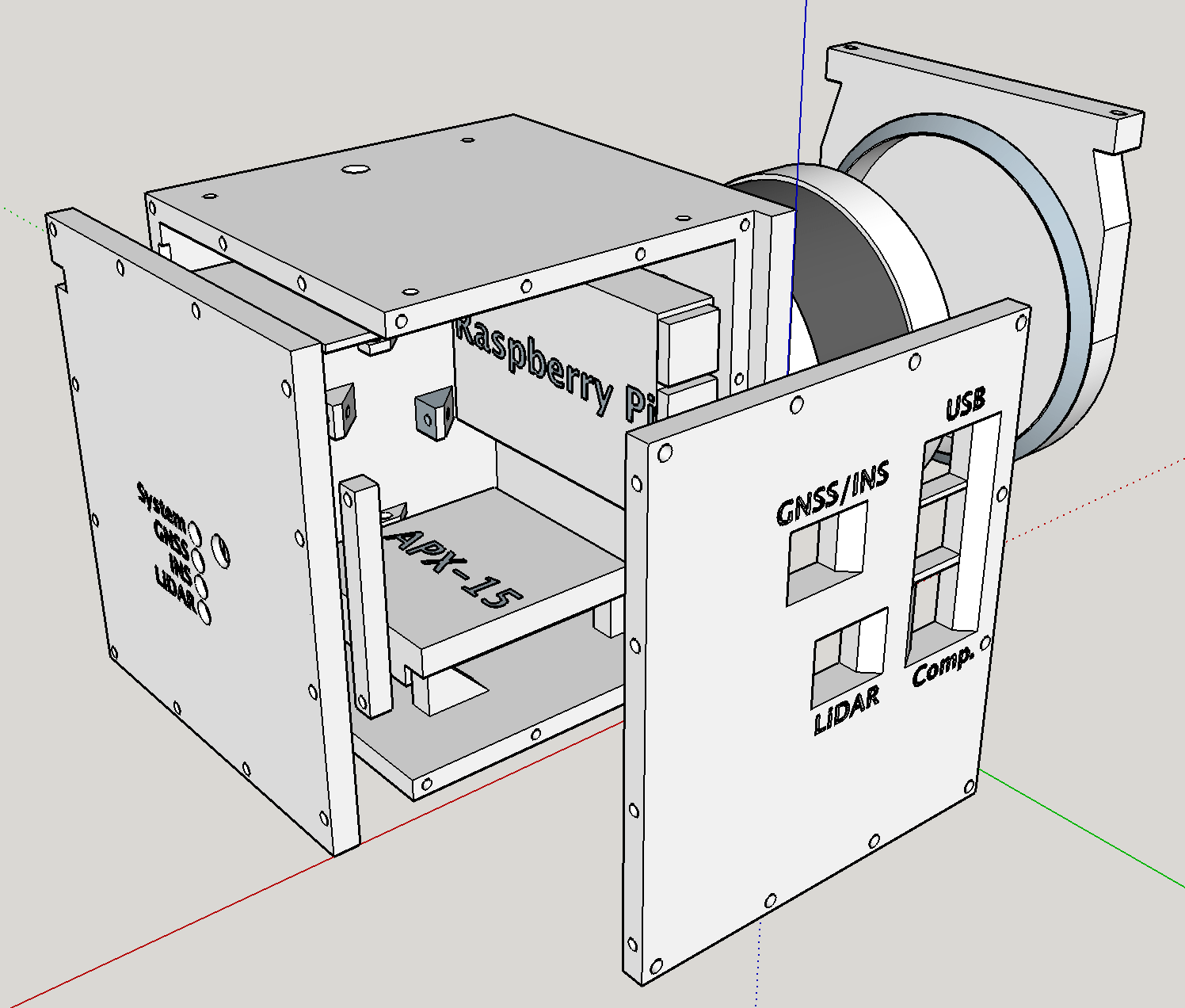
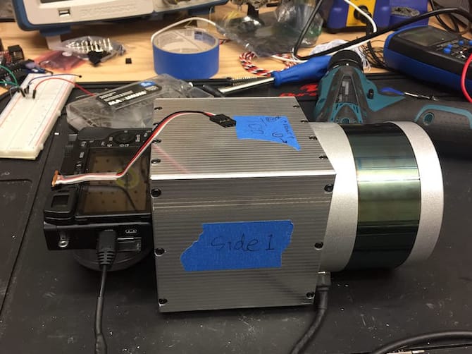
Once the initial round of fixing hardware bugs was finished, and a working data-processing procedure was in place, the next task focused on designing and manufacturing a small, strong, and lightweight enclosure to house all the individual sensors and electronic components safely. The enclosure’s design was iteratively improved using the free software, Trimble SketchUp. Desktop 3D printing manufacturing techniques were employed to produce the multiple iterations of the OpenMMS sensor enclosure quickly and inexpensively. Carbon fiber infused PLA plastic filament was the material used to create the sensor enclosure. Thanks to the unique characteristics of additive manufacturing techniques, the mounting location for the Velodyne VLP-16 lidar sensor within the enclosure had a 3mm thick steel washer embedded within the PLA plastic.
Thanks to the precise design capabilities of Trimble SketchUp, and the excellent manufacturing tolerances of the 3D-printers, the lever-arm offsets between the GNSS antenna, the Inertial Measurement Unit (IMU) and the Velodyne VLP-16 could be accurately and precisely determined without the need for manual measurements. The boresight misalignment angles, between the IMU and the Velodyne VLP-16, were determined by analyzing overlapping strips of point cloud data and manually identifying common points. Least-squares analysis of the lidar observations and the SBET data for the common points produced an estimate for the boresight misalignment angles. Accurately estimating these calibration parameters was a vital task and one that required time and research to complete.
Results
The 1st generation OpenMMS sensor was used regularly over a short period to rigorously test the hardware design, data collection procedures, and the data processing workflow. Testing was performed with the sensor mounted to an automobile and for data collection periods of no more than 30 minutes. As expected, additional hardware and procedural issues arose as a result of the testing. Slowly but surely, the problems were identified, patched, retested, and surpassed. The initial testing period finished when the sensor performed reliably and repeatedly over the same project area.
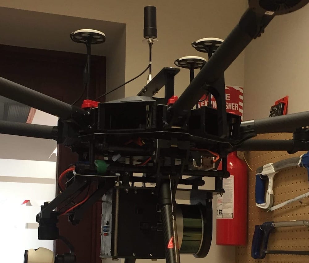
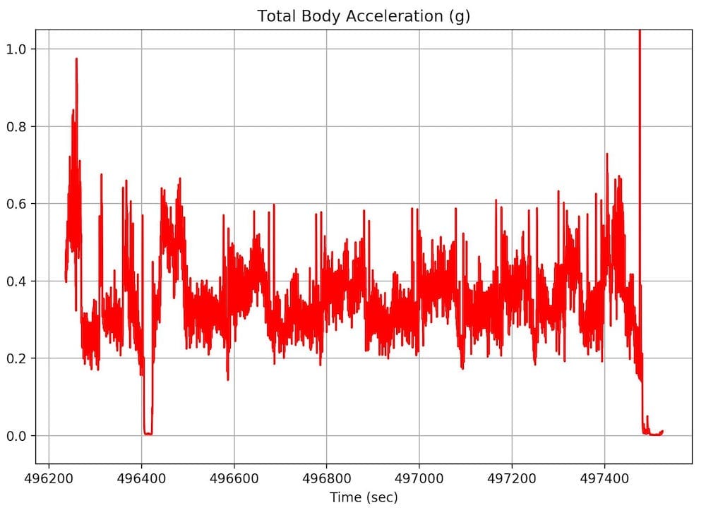
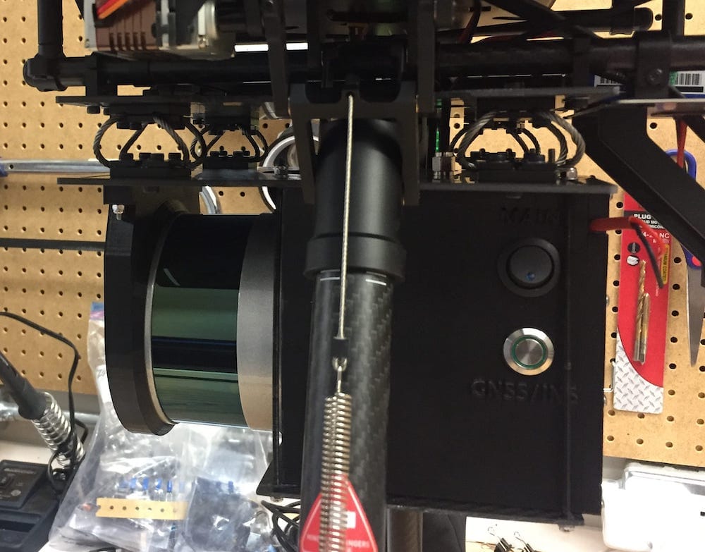
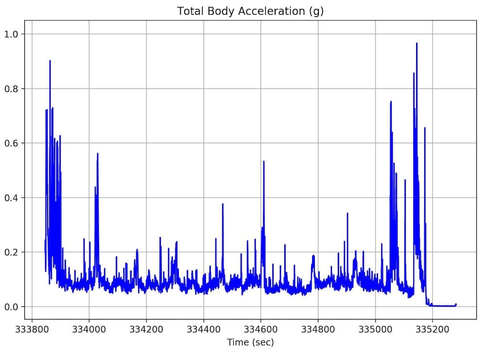
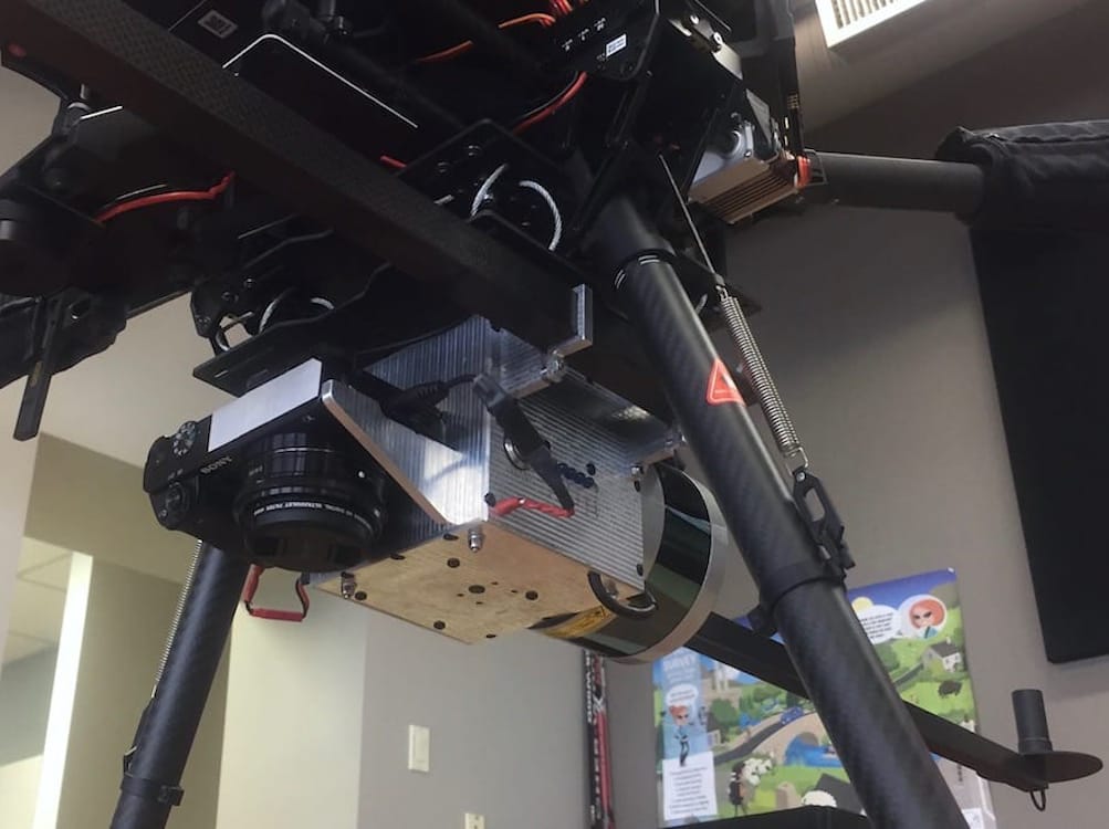
The final aspect of the 1st generation OpenMMS development project involved mounting the sensor to the underside of a remotely piloted aerial system (RPAS). The ubiquitous DJI M600 Pro RPAS, was selected as the most suitable aerial vehicle to use, due to its extensive use within the RPAS industry and excellent reputation. The DJI M600 Pro provided several mounting brackets/systems for installing unique payloads on the aerial vehicle. The first mount used for the OpenMMS sensor rigidly mounted the sensor to the DJI M600 Pro. While testing the rigidly mounted sensor, it was discovered that the APX-15 IMU was very sensitive to vibrations/accelerations experienced during normal RPAS operations. These increased vibrations were degrading the precision of the attitude observations and, therefore, degraded the accuracy of the georeferenced point cloud dataset. As a result, market research was conducted to determine if any vibration dampening solutions, specifically for the DJI M600 Pro, were already available. A vibration dampening solution offered by Standard Tech Operation was selected for the OpenMMS sensor. After changing the mounting system to incorporate the vibration dampening mechanisms, the unwanted vibrations were significantly reduced, and therefore the georeferenced point cloud dataset was also improved.
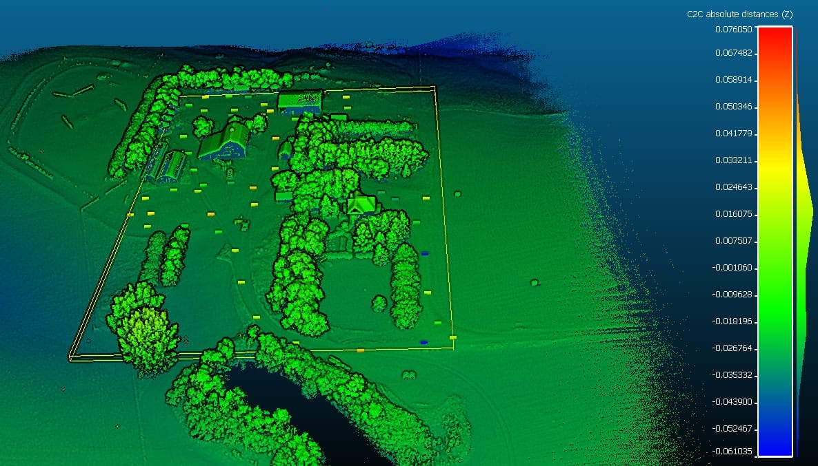
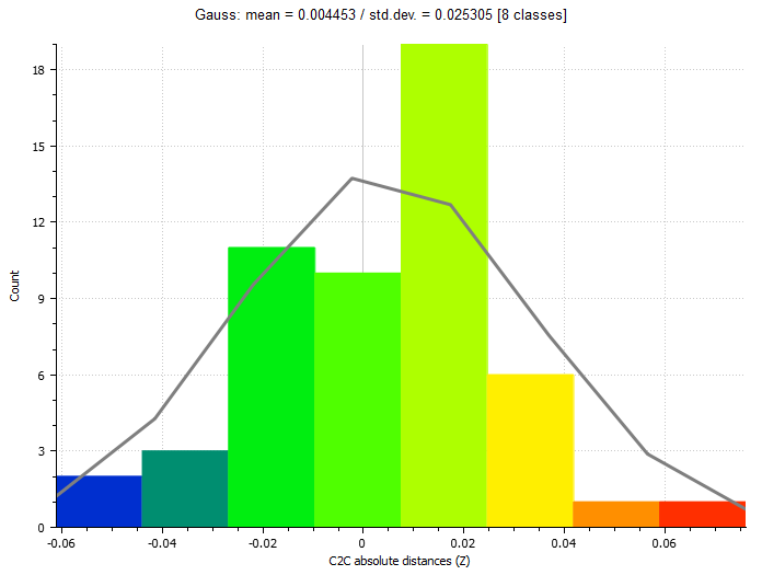
However, because the GNSS antenna for the APX-15 was still rigidly mounted to the RPAS body frame, and the IMU was now being dampened, the lever-arm offset values between the GNSS antenna and the IMU could no longer be considered constant values. The GNSS antenna was repositioned to be closer to the IMU, as well as centered directly above the IMU (Z-axis direction) to minimize the impacts of these introduced errors. The sensor’s error budget was still dominated by the uncertainties of the IMU attitude angles and the lidar range observations. After recalibrating the GNSS antenna lever-arm offsets via a ground-based total station intersection survey, an initial accuracy assessment of the created point cloud was performed. The figures below illustrate the vertical coordinate differences between ~ 50 ground points, surveyed via GNSS Real-Time Kinematic (RTK) techniques, and their closest point observation within the OpenMMS produced point cloud.
The OpenMMS Version 0.9 (Beta) sensor project was officially completed on July 25th, 2017. The final weight of the sensor was measured to be 2.25 kg.
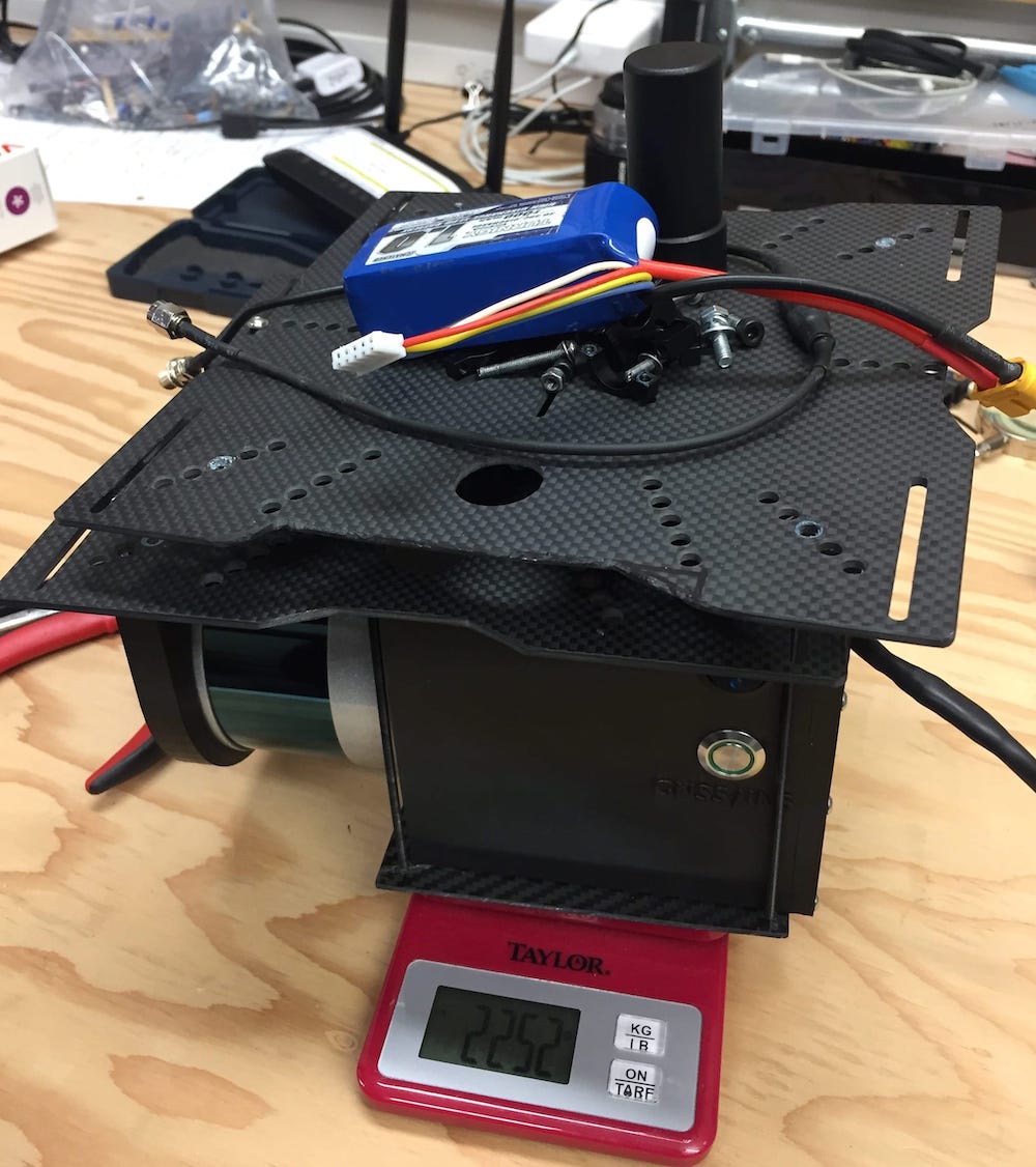
Fig A.12. Weight of Beta sensor, including all mounting hardware
Design, Manufacture and Assemble
OpenMMS Open-Source Hardware License
This documentation describes Open Hardware and is licensed under the CERN-OHL-S v2 license.
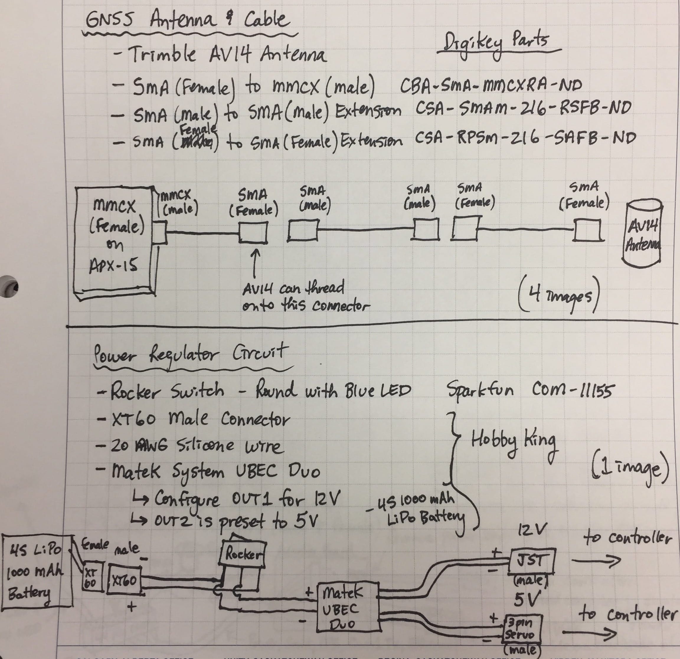
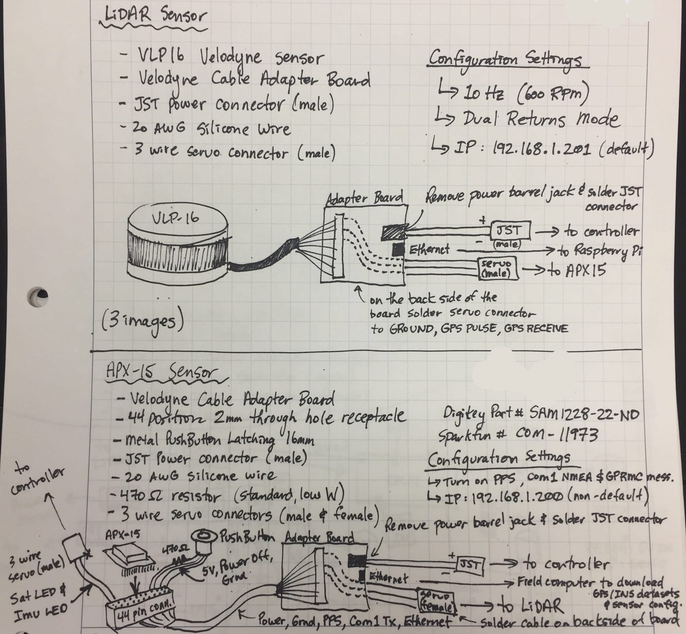
View the OpenMMS Open-Source Licenses for more details.The images and files below represent all of the documentation created for the 1st generation OpenMMS Version 0.9 (Beta) sensor. It is included here to illustrate the ‘early days’ of the project and showcase the project’s progression. The documentation is incomplete (and that’s putting it nicely)! All of the individual parts for the 3D-printed case were assembled using metric 3mm bolts (varying lengths) and Nyloc nuts (where necessary). A crude parts list can be created by viewing each of the ‘schematic’ sheets below. Parts’ source information (e.g., Digi-Key or Sparkfun Part No.) is included when available. Click here to download ALL the documentation files (.ZIP)
B. OpenMMS Sensor (Version 1.2)
Overview
For the OpenMMS Version 1.2 sensor, several new development goals were established. Some goals were identified by comparing the expected versus the achieved performance, functionality, and operations of the Beta sensor. While other goals focused on bringing new and additional functionality to the OpenMMS platform. The OpenMMS Version 1.2 sensor project began in May 2018. The major goals of the project were:
1. Install and integrate the following new components into the system.
2. Design and manufacture Printed Circuit Boards (PCBs) for connecting the system components.
3. Design and manufacture an aluminum case for the system.
Make it lightweight and as small as possible.
Create a quick-release mounting system for the APX-18’s dual GNSS antennas that is lightweight and rigid, and does not interfere with the normal operations of the DJI M600 Pro RPAS.
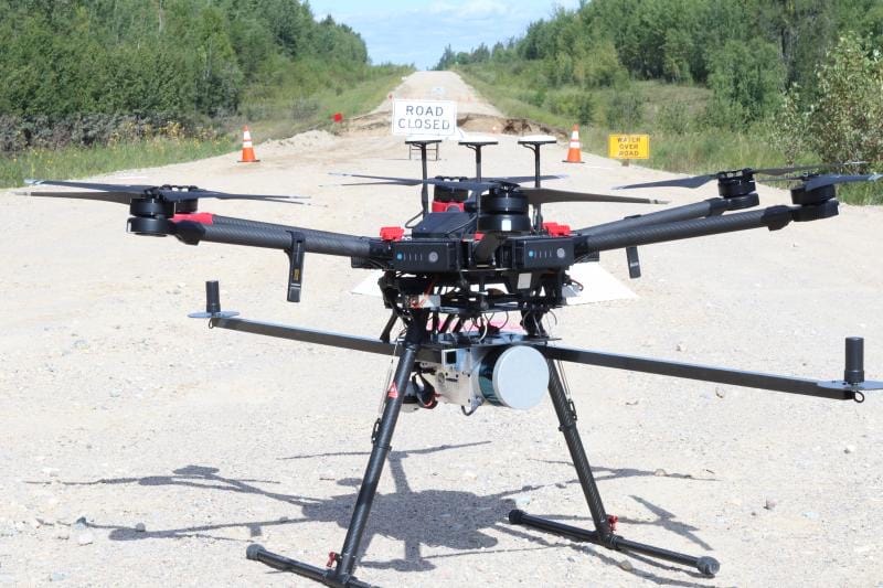
Fig B.1. OpenMMS Version 1.2 Sensor ready for takeoff on a DJI M600 Pro
Results
The OpenMMS Version 1.2 sensor project was completed in June 2019. All three of the project’s goals were accomplished, and the final manufactured sensor was sleek, secure, and easy to operate. With the addition of the Sony A6000 camera, the electronic systems increased in complexity, and the sensor firmware needed to be modified.
A new TTL serial communication connection was made between the Applanix APX-18 GNSS-INS sensor and the Raspberry Pi 3 computer. The serial connection allowed the Raspberry Pi computer to collect a dataset containing the real-time position and orientation (trajectory) estimates for the Velodyne sensor, which were computed by the APX-18. The accuracy of the position estimates would be on the order of autonomous GNSS positions (i.e., 1.5-3.0 meters) while the accuracy of the orientation estimates would be around 0.1 degrees. The benefit of collecting this new real-time trajectory dataset was that it was now possible to use it along with the Velodyne lidar observations to compute a lower accuracy point cloud while still at the project site location. The lower accuracy point cloud provided a valuable, and much needed, quality assurance check on the individual sensors’ datasets almost immediately after each flight/data collection campaign. The figure below illustrates a lower accuracy point cloud. It was processed using an older quad-core 1.8 GHz Windows laptop in ~ 2 mins. The point cloud data has been colorized based on the heading of the Velodyne sensor at the time of data collection (i.e., this figure illustrates the data collected per flight line).
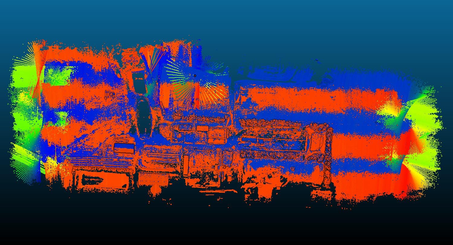
Fig B.7. Field processed point cloud for QA purposes
Gremlin
An inconsistency ‘gremlin’ was identified within the operations of the OpenMMS Version 1.2 sensor. To remove small, though noticeable, systematic errors within the resulting point cloud, every flight was required to be analyzed to estimate an optimal set of boresight parameters for the lidar sensor with respect to the IMU. It is believed that the boresight parameters are not, in fact, physically changing from one flight to the next. But instead, by re-optimizing the boresight parameters, the unknown systematic errors could be reduced. Therefore, the unknown systematic errors must be correlated with the boresight parameters.
Two leading theories for the cause of the systematic errors are, the sensor’s motherboard was located too close to the APX-18 sensor and was producing electrical interference that was biasing the IMU observations. Secondly, the IMU’s unconventional mounting with respect to the vehicle’s reference frame may have been introducing some unwanted effects. Instead of trying to introduce incremental changes within the electronic systems of the sensor, to see if they have any impact on the sensor’s consistency, it was determined that it would be best to redesign the sensor completely. As a result of this conclusion, the OpenMMS Version 1.2 sensor project was officially retired as of March 23rd, 2020.